Captain Foldback
| Tech Tips from Captain Foldback |
|
Creating a Leslie 122-style
connector kit from a 147-style kit
(not intended for console organs such as B-3)
Scenario: You have a Leslie 147-style connector kit either already fitted in your organ or removed from another organ, that you want to use with your Hammond and Leslie. This article describes how to convert the so-called 26-1 connector box often found in the 147-style connector kit, into a 122-style connector kit.
Why?: Organs of other brands than Hammond may often be found at a low price (or even for free). These organs may be brands like Conn, Wurlitzer, Thomas, Lowrey, Gulbransen, Elka, Farfisa - the list goes on. Many of these 'other' organs were used with Leslie speakers and most of these would include the Leslie connector kit. Also, many Hammond spinets were wired for Leslie 145/147 cabinets. If you want to use a Leslie 122 or similar with your spinet, this would help you as well.
Disclaimer:
The instructions given may not match whatever kit you have. There are variations
in the different Leslie kit styles, even if the 26-1 conector chassis should be
pretty much standard. Do not try this conversion if you do not have a basic
understanding of electronics. High (possibily lethal) voltages will be present
in the circuitry when operating, so be extremely careful with your work,
neatness is important.
This modified kit will work poorly with a B-3. It is intended for a single
single ended output as found in L-series, M-series, T-series and E-100 series
organs. In a pinch the kit would work with an A-100.
How: Look at the circuit diagrams below, then read the instructions. If you need more information before heating the soldering iron, you may look at the Leslie schematics, manuals and the Leslie cable pin-out guide - all found elsewhere on this website.
What: I have based the instructions on the following components:
+jumper wire as appropriate
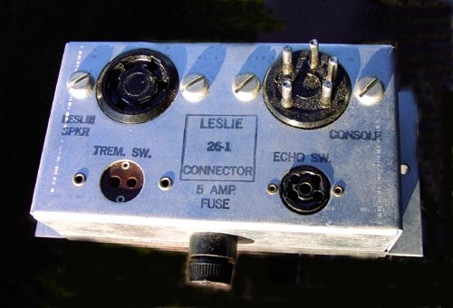
This is the starting point, the stock version of a 26-1 chassis:
In the instructions, the connector marked 'Console connector' is called the 5-pin connector. The socket marked 'Leslie speaker' is called the 6-pin connector. The tremolo switch shown is closed for the 'chorale' position. This is true for the original 147-style cirquit, but not for the 122-style control. If your kit includes a working tremolo switch wired this way, you need to rewire the switch or alternatively rotate the switch assembly inside the 'half moon' housing (see item 10/ in the list below).
The end result should be a circuit similar to this:
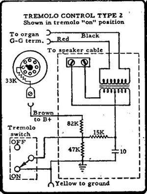
Please note:The two wires at the top of this diagram marked 'To organ G-G term.' are connected differently in this adapted control kit. The black wire goes to ground, the red goes to the echo output from the 26-1 chassis. The colour codes may not match what you have. In any case, the transformer primary is the one with two wires, the secondary has three wires.
Instructions:
Prepare 26-1 chassis
1. Remove jumper from pin 4 to pin 5 on 6-pin connector, leaving pin 4 connected
to the fuse.
2. Remove jumper from pin 3 on 6-pin connector to tremolo switch socket (leave
connection from pin 2 to other side of switch socket).
3. Remove jumper from pin 2 on echo switch socket to pin 6 on 6-pin connector.
4. Move wire on 6-pin connector from pin 1 and add it to pin 2 (so that pin 1 on
5-pin connector is connected to pin 2 on 6-pin connector). Pin 2 on the 6-pin
connector is now ground, as is one side of the tremolo switch socket (so both can be
used as a ground tie-point).
Prepare new components and new wire connections
5. Take one 47k/1W resistor and connect it between the pins of the tremolo
switch socket
6. Take one 100k/2W and one one 15k/0.5w resistor and join them together.
Connect 100k end to pin 5 on 6-pin socket and the joint of the two resistors to
small (non-ground) pin of tremolo switch socket.
7. Take one 10uF/450V (radial lay-out preferred) and connect as follows:
Negative pole to ground (either tie-point, see above (4)) - positive pole to free
end of 15k resistor mentioned above. The joint of the capacitor and the 15k
resistor is to be connected to a new external wire connection to the centre tap
of the control transformer secondary (see tremolo control circuit diagram above).
8. Connect one 16ohm/10W resistor between ground and pin 2 of echo switch
socket.
9. Prepare the following external wire connections for the control transformer:
Tremolo control
10. Open half-moon switch and turn switch assembly 180 degrees so 'switch
closed' is now tremolo.
11. Connect the five transformer wires to the five external connection wires
from the 26-1 box - may be skipped if control transformer has been hard-wired.
12. Mount transformer next to 26-1 box, connect Leslie speaker and test.
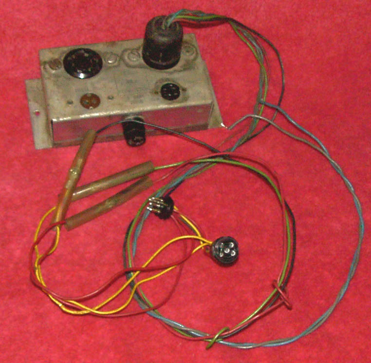
I am sorry for the bad picture quality of the following pictures. I will try to get better ones. The pictures show the 26-1 before modification.
Happy soldering!
May 31, 2004
-Captain Foldback