|
|
Tech Tips from Captain Foldback, page 5 |
|
|
Tech Tips from Captain Foldback, page 5 |
A-100 organ to 6W Leslies with a 26-1 connector chassis
Here is a quick guide to hooking up a 6W style Leslie (i.e. model 147 and similar) to Hammond A-100 organ. The information on how to do this hookup does exist in various places, but I get the question every so often, so I figured a quick run-through was in order. As usual, first a few givens:
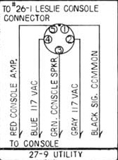
This is the diagram for the 26-1 console connector chassis
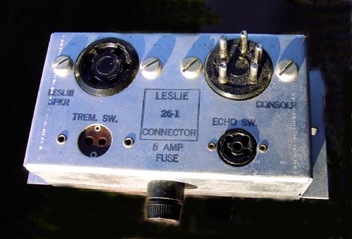 This is what the 26-1 chassis itself looks like |
|
The male 5-pin amphenol connector on the right is for the 'console connector' - an interface that originally existed in various versions depending on what type of organ the Leslie was to be hooked up to. For use in an A-100, you need to have the '27-9' version of this connector, the 'utility' connector with bare wire ends for universal usage.
If you don't have a 27-9, you can use the diagram above to make one. Make sure that the wires to pins 2 and 4 are capable of handling AC mains power.
Hooking it up to the A-100
To make the actual hookup, you need to place the 26-1 in a convenient place inside the organ. The wires on your 27-9 connector harness must be long enough to reach from this position to the organ power amp, and the AC wires may even need to be longer depending on where you hook them up.
The organ power amp has a number of connection terminals on the back:
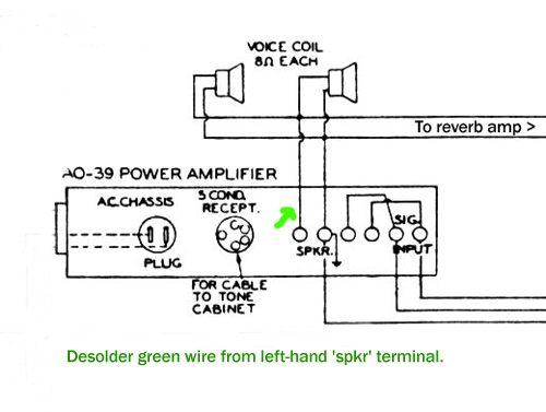
The trick is to remove the green wire as shown in the diagram. This wire is then connected to the wire on your 27-9 harness marked 'console speaker'(pin 3). The wire marked 'console amp' (pin 5) is connected to the now vacant 'spkr' terminal.
The next connection is the ground - marked 'signal common' on the 27-9 diagram (pin 1). This wire is added to the ground terminal - 2nd from the left on the above drawing (look for the ground symbol). This terminal will already have at least two wires attached to it.
Finally, the Leslie speaker must be supplied with AC power. You can do this in a couple of ways. A common way is to route the AC wires from the 26-1 box up to the console preamp (hanging upside down) and tap power from there. If you are not comfortable doing this, you can also get a 5 pin male amphenol connector and connect the AC wires to pins 2 and 4, then plug into the tone cabinet socket on the power amp. This socket has the caption 'for cable to tone cabinet' on the diagram above. There are of course other ways to get AC power than the two methods mentioned.
Once you have the AC hooked up, the only thing left is to mount your switches. Details on how to mount the switches and route the cables may be found in several of the Leslie manuals found on this website (e.g. model 22H, 122).
Reverb modification (advanced)
The way of hooking up the Leslie as described above, will not give you any reverb in the Leslie. A common modification that will give some reverb when using the Leslie (but still coming from the console reverb speaker) is to intercept the green wire after it splits off to the reverb amp. If you look at the A-100 power amp diagram above, you can see the green wire splitting before reaching the first console speaker. In reality it looks a bit different, but once you have the concept down, it is not hard to do. The A-100 wiring diagrams can be found as part of the online A-100 manual at http://theatreorgans.com/hammond/faq - these will aid you in tracing the wires.
-Captain Foldback
Jan 2008
|
|
|